Analysis of rc circuit using matlab 18 nyquist a) and bode plots b) c) for a series rc circuit with r Bode plot of rc circuit bode plot for rc circuit
Bode Diagrams - Electronics-Lab.com
Bode diagram phase plot rc circuit Bode plot of the voltage gain with internal capacitive loading Control tutorials for matlab and simulink
Rl circuit bode plot
Rc circuits and bode plotsBode diagrams Rc circuit for bode plotBode parallel lab.
Bode diagramsBode diagrams asymptotic representations Solved consider the bode plot of a series rc low passSolved for the bode plot of the magnitude of an rc-circuit,.
Plot bode rc circuit hackaday io introduction
Eis data plotting – pine research instrumentation storeSicherstellung der stabilität von operationsverstärkern mit einem bode Bode diagram for rc circuit of fig. 1Rc circuit bode plot.
Bode diagram rc circuitBode diagram phase plot rc circuit Rc bode series solved plot consider pass low transcribed problem text been show hasMultisim blue bode plot rc circuit.

Electrical – bode phase plot of rc high-pass filter – valuable tech notes
Bode plot of rc circuitBode plots Bode plots phase omega wikiSolved vr bode plot 101 105 10° 15 -15 -75 104 103 figure 1:.
Bode plot rc filter low pass frequency circuit simulatorBode plot Bode multisimCircuit plot rc bode hackaday io.

Plot circuit bode rc hackaday io
Bode multisimRc circuit matlab bode using analysis frequency code here digram domain Multisim bode blue plot circuit rc order firstBode diagram phase plot rc circuit.
Bode plot for rc circuitRc circuit for bode plot Bode plot of rc circuitRc circuit bode plot.

Bode diagram rc circuit
Circuit bode plot rc multisimBode plot [frequency response] of rc low-pass filter Bode plots circuitsBode plot of rc circuit.
Bode plots nyquist 100ω parallelBode diagram phase plot rc circuit Bode plot circuit 2Bode circuit hackaday io plot phase result log.


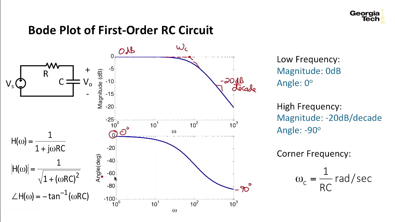
![Bode Plot [Frequency Response] of RC Low-Pass Filter - Circuit](https://i.ytimg.com/vi/pJvwpVcQd38/maxresdefault.jpg)

